WATTS ANTENNA COMPANY’S MODEL GP5-A1
HIGHLY DIRECTIONAL BEAM-STEERED IMAGE GLIDE PATH WIDE APERTURE ANTENNA
CATEGORY I/II/III INSTRUMENT LANDING SYSTEM
FEATURING MINIMAL CRITICAL & SENSITIVE AREAS
We’re Making History!
Watts Antenna Company’s model GP5-A1 provides smaller critical areas for Category I/II/III Instrument Landing Systems. Watts has recognized that worldwide engineering practices employed to overcome difficult site problems with image glide path (GP) antenna systems indicate that the antenna lateral radiation pattern is being substantially challenged in the modern airport environment. Introduction of larger aircraft such as the Airbus A380 and airport efficiency constraints are also driving a reduction in the size of the critical area of the Glide Path system in order to take advantage of the larger jets and to increase airport capacity.
The Model GP5-A1 Antenna element, nomenclature GP5-A1, has been designed and manufactured by Watts Antenna Company to provide highly accurate guidance information to an approaching aircraft while permitting increased flow of aircraft traffic in the vicinity of the GP tower. The initial development was undertaken by the manufacturer starting in the fourth quarter of 2003.
Features
- Directive, narrow beam produces optimum pattern in airport multipath environments.
- Asymmetric radiation pattern provides greater use of all taxiways in the vicinity of the GP mast.
- Rejects sources of both static and dynamic multipath on the side of the runway containing the tower.
- No shim adjustment necessary.
THE PROOF IS IN THE CRITICAL AREA COMPUTATIONS!
M-ARRAY (Capture Effect) Configuration For Critical Area Comparisons Of Watts MODEL GP5-A1, Kathrein & FA8976 Antenna Arrays
GP5-A1 M-Array/CE w/Additional -6 Degree Rotation
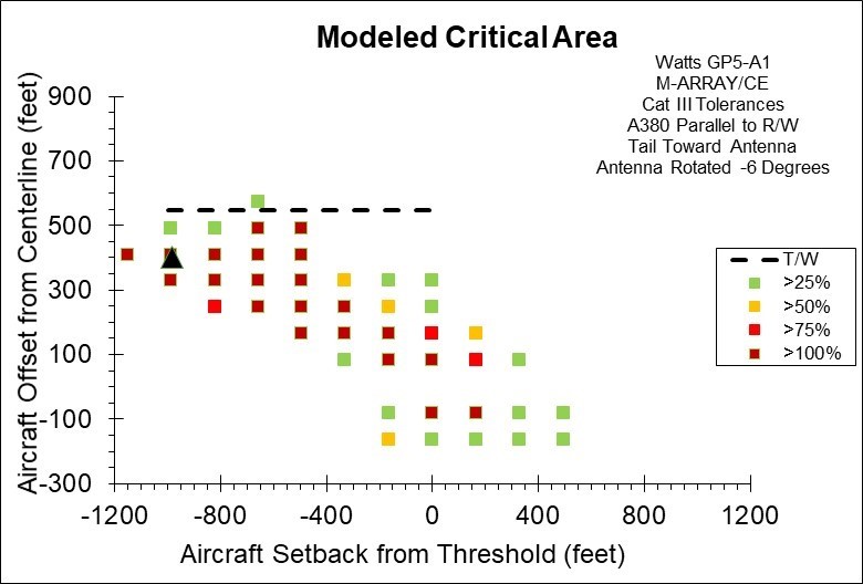
Figure 1. Computed ILS Glide Slope Critical Area for an Airbus A380 Parallel to the Runway Using the Watts Model GP5-A1 Beam Steered Directional Antenna in M-Array Configuration, also referred to as Capture Effect (CE). This Figure Shows the Addition Critical Area Reduction Achieved by Mechanically Rotating the Already Canted Beam by an Additional 6.0 Degrees Toward the Runway. (The Dashed Line on the Plot Represents a Taxiway Offset Distance Where the Tower to Wingtip Separation is Only 5 Meters (16.4 Feet). The Black Triangular Shape Represents the Location of the Glide Slope Tower.)
GP5-A1 M-Array/CE w/Additional -3 Degrees Rotation
GP5-A1 M-Array w/o Additional Rotation
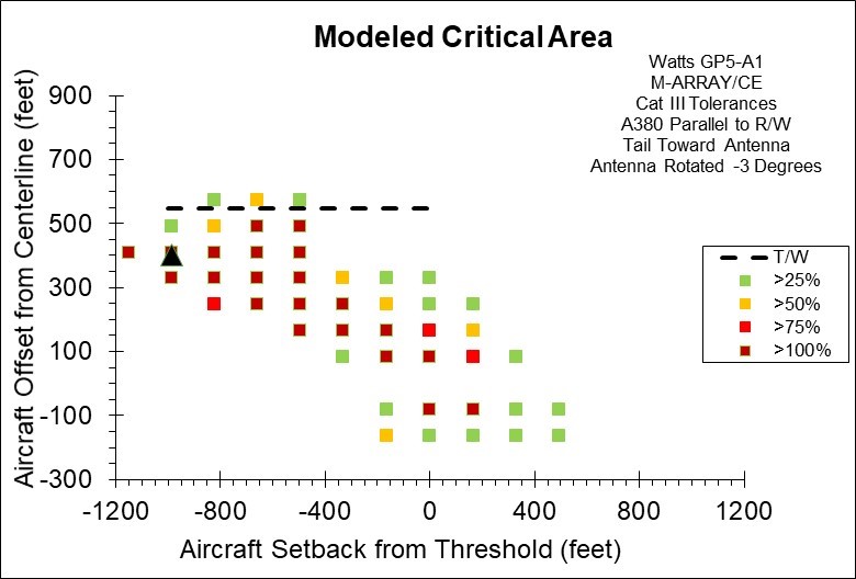
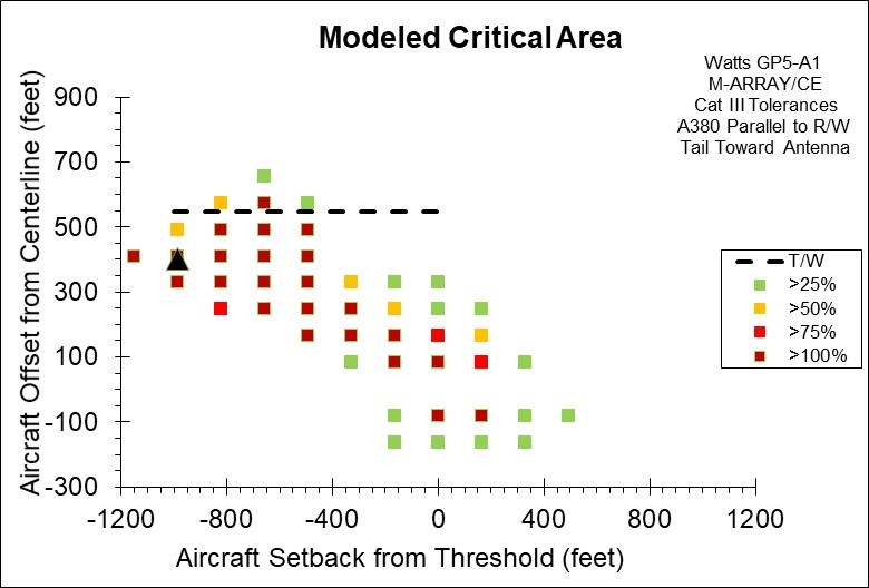
Figure 2. Computed ILS Glide Slope Critical Area for an Airbus A380 Parallel to the Runway Using the Watts Model GP5-A1 Beam Steered Directional Antenna in M-Array Configuration, also referred to as Capture Effect (CE). This Figure Shows the Addition Critical Area Reduction Achieved by Mechanically Rotating the Already Canted Beam by an Additional 3.0 Degrees Toward the Runway. The Dashed Line on the Plot Represents a Taxiway Offset Distance Where the Tower to Wingtip Separation is Only 5 Meters (16.4 Feet). The Black Triangular Shape Represents the Location of the Glide Slope Tower.
Figure 3. Computed ILS Glide Slope Critical Area for an Airbus A380 Parallel to the Runway Using the Watts Model GP5-A1 Beam Steered Directional Antenna in M-Array Configuration, also referred to as Capture Effect (CE). The Dashed Line on the Plot Represents a Taxiway Offset Distance Where the Tower to Wingtip Separation is Only 5 Meters (16.4 Feet). The Black Triangular Shape Represents the Location of the Glide Slope Tower.
Kathrein M-Array/CE
FA8976 M-Array/CE

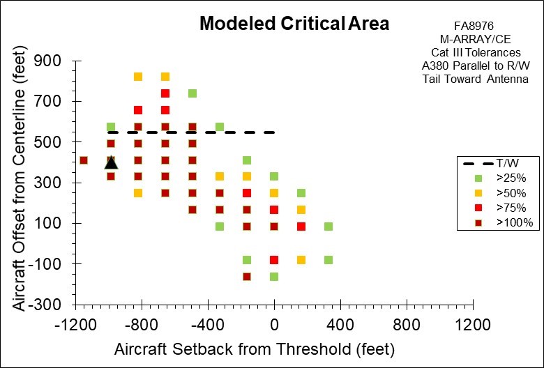
Figure 4. Computed ILS Glide Slope Critical Area for an Airbus A380 Parallel to the Runway Using the Kathrein Antenna in M-Array Configuration, also referred to as Capture Effect (CE). The Dashed Line on the Plot Represents a Taxiway Offset Distance Where the Tower to Wingtip Separation is Only 5 Meters (16.4 Feet). The Black Triangular Shape Represents the Location of the Glide Slope Tower.
Figure 5. Computed ILS Glide Slope Critical Area for an Airbus A380 Parallel to the Runway Using the FA8976 Antenna in M-Array Configuration, also referred to as Capture Effect (CE). The Dashed Line on the Plot Represents a Taxiway Offset Distance Where the Tower to Wingtip Separation is Only 5 Meters (16.4 Feet). The Black Triangular Shape Represents the Location of the Glide Slope Tower.
Model GP5-A1 Specifications
| Company: |
Watts Antenna Company |
| Antenna Type: | Directional Beam-Steered Image Glide Slope Antenna |
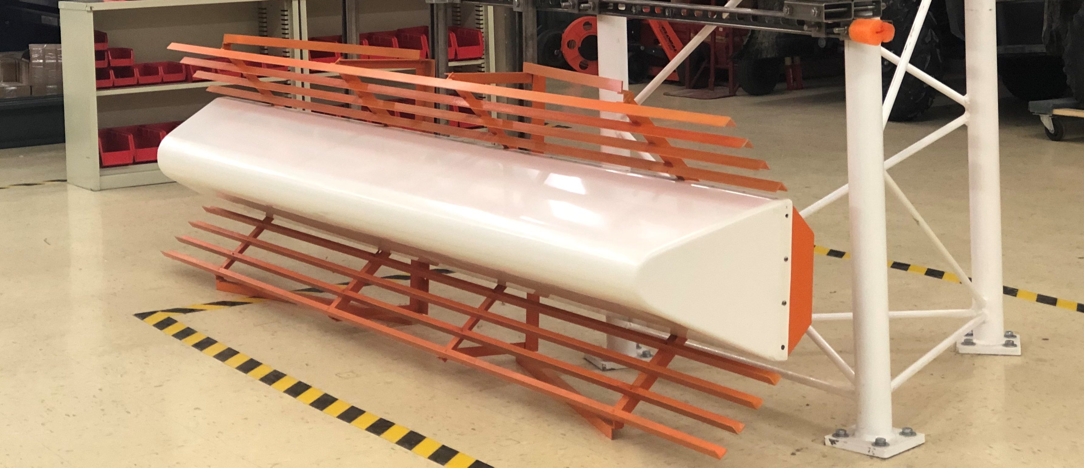
| Nomenclature: | Model GP5-A1 |
| Color: | International Orange and White |
| Coating: | Icephobic |
| Frequency Range: | 329.0 to 335 MHz |
| Polarization: | Horizontal |
| Radome Type: | Full Cover-Fiberglass |
| Reflector Type: | 90 Degree Trough and Corner |
| Maximum Power: | 50w CW |
| Input: | Type N Female Connector |
| Pattern Type: | Asymmetric |
| Gain: | > 13 dBd |
| Beam Displacement: | > 6 Degrees Nominal * See Note |
| -3 dB Beamwidth: | 23 Degrees Nominal |
| Sidelobe Suppression: | 25 dB Nominal |
| Front-to-Back Ratio: | >21 dB Nominal |
| Input Impedance: | 50 Ohms Nominal |
| VSWR: | < 1.25 to 1 |
| Distribution Loss: | < 1 dB |
| Distribution Isolation: | > 22 dB Between Ports |
| Monitor Impedance: | 50 Ohms Nominal |
| Monitor Output: | Type N Female Connector |
| Monitor Coupling: | > 20 dB Nominal |
| Temp Range: | -55 to +75 Degrees C |
| Lateral Thrust: | 1450 N at 160 km/h |
| Max. Wind Velocity: | 200 km/h (incl. 1/2″ radial ice) |
| Length: | 2.69 Meters (106 Inches) |
| Height: | 79 CM (31 Inches) |
| Weight: | 34.02 KG Approximate (75 lbs) |
| Heaters: | Not Needed |
| NOTE: | Up To An Additional 6 Degree Physical Beam Displacement In Either Direction With Shim Kit |
| Material: | Dipole System: Aluminum.
Reflector: Aluminum w/ Icephobic Coating (orange). Radome: Fiberglass (white). All Screws and Nuts: Stainless Steel. |
| Scope of Supply: | Antennas w/ Mounting Hardware, Shim Kit and Instruction Manual. |
| Mounting Hardware: | B-Line 304 Stainless Steel Mounting Struts and Components. |
| Lightning Protection: | Antenna is DC Grounded Including Inner Conductors. |
WATTS’ GP SERIES CATEGORY I/II/III INSTRUMENT LANDING SYSTEM ANTENNAS
FEATURE MINIMAL CRITICAL AND SENSITIVE AREAS
THE GP5-A1 IS THE ANSWER TO SMALLER CRITICAL &
SENSITIVE AREAS AND GREATER AIRPORT CAPACITY