Watts Antenna Company’s End-Fire Glide Slope Antennas
NON-IMAGING END-FIRE GLIDE SLOPE ANTENNA
Three Models Available
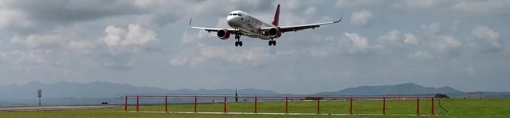
End-Fire Antenna Systems are intended for runways having a limited amount of flat terrain and difficult site conditions such as hillsides, mountainous regions, and waterside locales. The functioning of the system is essentially unaffected by adjacent low ground or body of water with tidal variations and because it is the only GS antenna allowed within the RSA, it can be placed on either side of the runway to avoid terrain reflections of the signal-in-space in the approach region.
They are also excellent for highly developed areas such as Miami International Airport who recently installed one (to make room and add an additional taxiway), because the manner in which they focus the reflected ILS signal-in-space, frees real estate inside and outside of the airdrome to allow room for additional development opportunities e.g. runways, taxiways, hangers, hotels, casinos, office buildings, multimodal transportation systems, etc.
Where the terrain is physically unsuitable, environmental regulations prohibit earth moving, or it is not economically feasible to prepare the required ground plane for an image-type glide slope, the Watts End-Fire is the answer when no one else can do it………. the tough site solution.
“END-FIRE”
END-FIRE systems provide airports with cost effective ILS support. These antenna systems are intended for runways having a limited amount of flat terrain. Use of End-Fire allows airports to avoid the high cost of ground preparation and civil work that can amount to more than a million dollars. End-Fire can also be installed near the runways edge because of its proven frangible design; this is helpful when considering environmental situations.
Watts Antenna Company has delivered End-Fire antenna systems to airport sites in countries around the world. The first system was installed and commissioned nearly forty years ago at Rock Springs, Wyoming in 1979.
Airport Locations include:
– Large commercial airports with extensive international and domestic scheduled services
– Urban and suburban general aviation airports
– Mid-sized and smaller airports with active general aviation traffic in highly promoted tourist areas
– Military air stations
The company’s products, with the End-Fire Glide Slope Antenna Systems most widely-known, can offer numerous benefits over conventional image systems:
– Significant cost savings by avoiding expensive ground-plane conditioning
– ILS service where previously not possible or cost effective due to terrain
– Proven frangible low-profile design permitted “Next-to-Runway” installation
– Preserve wetlands or avoid high wetland relocation costs
– Waterside installations since the signal is not degraded by tidal variations
– Precision Glide Path guidance is achieved with narrow lateral radiation patterns that reduce multi-path signals from buildings or mountainous terrain
WATTS END-FIRE GLIDE SLOPE ANTENNA SYSTEMS
END-FIRE systems provide airports with cost effective ILS to support airport and economic growth important to local and regional marketplaces. The systems provide final approach glide path information to a landing aircraft, enabling the pilot to maintain a constant descent angle until contact is made with the runway and the landing completed.
Watts END-FIRE antenna systems are intended for runways having a limited amount of flat terrain such as hillside, mountainous, or waterside locations and highly and densely developed locales. These systems are non-image in that the path angle is determined by the relative phase of the signals generated by the front main and rear main antennas. The functioning of the system is essentially unaffected by adjacent low ground or a body of water with tidal variations.
Because the End-Fire system does not require a prepared ground plane to reflect signal to approaching aircraft as image-type systems do, use of the end-fire allows airports to avoid the high cost of ground preparation and civil work that can amount to more than a million dollars. Also, if real estate is constrained due to development, wetlands, or other environmental considerations, the End-Fire system can be installed close to the runway edge due to its proven frangible design. The Watts END-FIRE system is the answer…the tough site solution.
END-FIRE antennas offer numerous benefits over conventional image systems:
- Provide ILS service where not previously possible or cost-effective due to terrain
- Significant potential cost savings can be achieved by avoiding expensive ground plane conditioning
- Provides reduced critical area size and limited airport land can be conserved due to the next-to-runway location
- Frangible, Low-to-ground design provides safety margins compared to close-to-runway obstructions requiring waivers
- Narrower lateral radiation patterns reduce multi-path from scatterers, such as buildings or mountainous terrain
- Confines aircraft to a narrower approach sector by providing fly-up guidance by capture-effect clearance signals in the lateral plane
- Provides up to 28% improvement over Sideband reference systems at sites with subtly-rising terrain or small scatterers beneath the approach path
- At severe upslope sites, the Model 107 Upslope systems offers improvement over conventional capture-effect systems since SBO cancellation is maintained at higher elevation angles to reduce multi-path
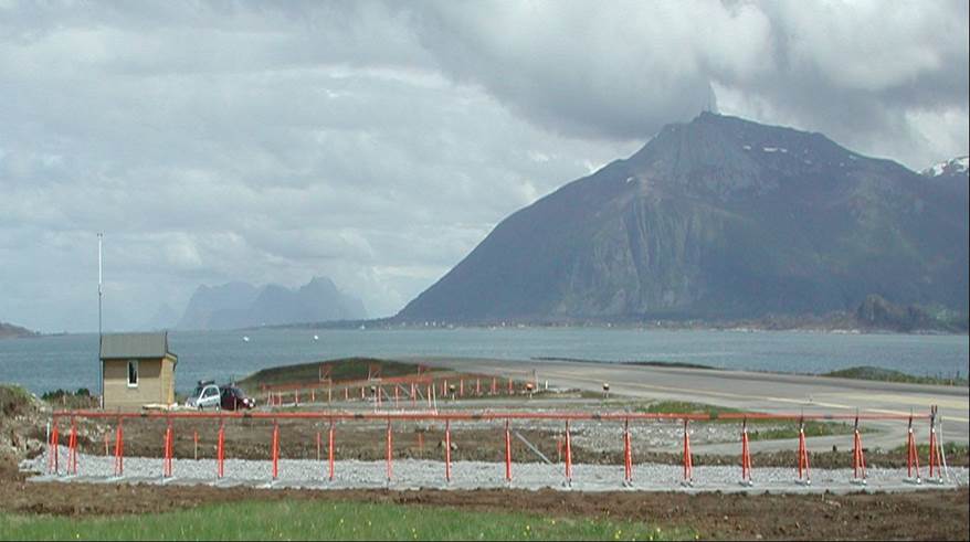
MODEL 105 END-FIRE SYSTEM, VIGRA, NORWAY
Watts Antenna Company manufactures the End-Fire glide slope antenna in two main configurations: the Model 105 and Model 106. The Model 106 is similar to the Model 105 but has shorter antennas with a sharper azimuth pattern. Neither is intended for severe up‑slope sites, which would require a vertical radiation pattern having suppressed guidance signal below the path.
The Model 107 Upslope produces such a pattern, using increased antenna spacing and the addition to the End‑Fire array of a third guidance antenna. In this case, the clearance signal pattern is also modified to fill in fly‑up signal below path, as well as to the sides. Developed subsequent to the Model 105, the Model 106 EFGS Antenna System and currently the Model 107 Upslope are a continuation of the effort started by Watts in 1970 to overcome inherent siting difficulties of image‑type glide slopes.
Over 60 END-FIRE systems have been delivered worldwide at commercial and general aviation airports, and military installations.
| LOCATION | MODEL 105 | MODEL 106 | TOTALS |
| United States | 22 | 24 | 46 |
| South Korea | 4 | 0 | 4 |
| Norway | 4 | 0 | 4 |
| Switzerland | 0 | 2 | 2 |
| Venezuela | 1 | 0 | 1 |
| India | 1 | 0 | 1 |
| Brazil | 2 | 2 | 4 |
| Colombia | 0 | 1 | 1 |
| China | 0 | 1 | 1 |
| TOTAL | 34 | 30 | 64 |
MODEL 105 & 106 END-FIRE GLIDE SLOPE ANTENNA SYSTEMS
| MODEL 105 THEORETICAL PATTERNS (CATEGORY I OR II)
The Model 105 END-FIRE system provides similar advantages to the Model 106 with an additional capability of meeting Category II requirements. The Model 105 has a course antenna -2 dB beamwidth of 13 degrees with an increased lateral proportional guidance area of 22 degrees. The increased proportional area, on the runway side, provides coverage to the threshold for Category II. |
 |
The Model 105 also incorporates a fast-action analog autophaser for improved path angle stability. It is designed for Category I or II sites with limited runway shoulder area and because of its frangible design, the system can be placed within 25 feet of the runway shoulder with only slightly more real estate than the Model 106. The system can be installed with minimal ground plane conditioning in the vicinity of the antenna. END-FIRE systems DO NOT REQUIRE image signals from the ground to form the path in space. The Models 105 and 106 perform well when the ground around the antenna rolls off significantly, such as with a mountaintop location, but are not intended for severe upslope sites. If a severe upslope site is under consideration, the Model 107 Upslope End-Fire Antenna System may be considered.
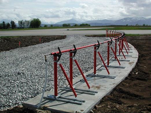 |
MODEL 105 END FIRE GLIDE SLOPE ANTENNA SYSTEM
INSTALLATION AT VIGRA, NORWAY SHOWING REAR MAIN ANTENNA
Note that the Model 106 System is shorter, having five sections (not eight as in the Model 105 picture above) |
MODEL 105 AND MODEL 106 THEORETICAL CDI PATTERN COMPARISON
MODEL 105 (CATEGORY I OR II)
MODEL 106 (CATEGORY I)
The graph at left shows the differences in the lateral coverage of two models of End-Fire systems. The Model 106 has 16 degrees of coverage on the runway side to provide guidance to the runway threshold for Category II approaches. Both models provide hard fly-up clearance signals to the sides of the proportional guidance area. The width can be adjusted to provide a hard fly-up condition near mountain slopes, increasing safety for corridor type approaches.
WATTS END-FIRE ANTENNA SYSTEMS attain significant performance advantages where site considerations dictate.
NARROWER HORIZONTAL RADIATION patterns reduce the possibility of multi-path from buildings, power lines, or terrain that is displaced from the antenna system. The reduced lateral radiation, compared to conventional image systems, allows additional flexibility for aircraft movement on taxiways and aircraft positioning to hold for take-off. With this type of application, and for Category I, the Model 106 is the best performer. The Model 105 provides similar benefits for Category II sites.
 One key to REDUCED COURSE ROUGHNESS with terrain irregularities is to limit the amount of Sideband Only (SBO) at low elevation angles. Not only can the End-Fire save the costs of earth fill, a performance improvement is also gained. A comparison of the vertical plane SBO patterns shows as much as a 28% improvement can be expected over a Sideband reference type image system at low elevation angles. This makes the Model 105 and Model 106 End-Fire systems desirable options when the site is marginal for a Sideband Reference, and when there is not real estate available to allow placement of a Capture Effect mast.
 MODEL 107 “UPSLOPE” END-FIRE GLIDE SLOPE ANTENNA SYSTEM
The UPSLOPE system provides improved performance over the conventional Capture Effect system at sites where rising terrain exists beneath the approach region. The SBO signal is reduced at low elevations and remains suppressed also at higher elevations. The area beneath the approach path and to the sides is filled in with fly-up clearance signals, meaning capture effect signal techniques are employed in both the lateral and vertical planes.
MODEL 105 AND MODEL 106 INTERFACE UNITS
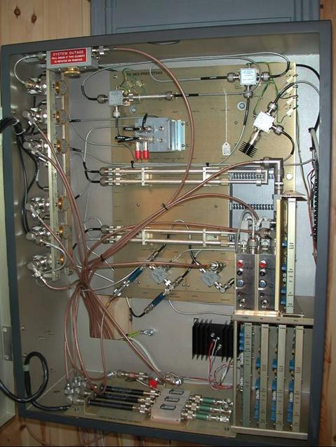
THE EF9 INTERFACE UNIT, a Model 105 is shown on here on a test bench at Watts Antenna Company, is a wall-mounted unit that contains the controls for adjusting the relative amplitude/phase of the signals, transmit and monitor, for the End-Fire System. The unit has a stand alone design that allows it to be interfaced with the transmitting and monitor electronics produced by virtually every manufacturer. The unit also contains additional monitor channels for the three mid-field monitors and the clearance antenna monitor. The interface unit needs Course CSB and SBO signals, Clearance signal, and +27 volts DC from the station transmitter. The Model 106 interface unit is nearly identical, excluding the autophaser assembly mounted on top of the card cage at the far right.
 SITING INFORMATION AND CRITICAL AREA:
The site chosen NEED ONLY provide a runway shoulder, graded normally, unobstructed in the area between the front and rear main antennas and to at least 500 feet forward of the front antenna. Placement of VASI systems or runway signs within this area can likely be accommodated through consultation with the manufacturer. The “CRITICAL AREA”, shown at right, is the area in which the movement of vehicles or aircraft may cause disturbance to the glide slope observed by an approaching aircraft. If installation is to be made on the side opposite to that shown, this drawing should be mirrored about the runway centerline. Layout of the system is accomplished with respect to a point known as the RPI. The RPI is the intersection of the straight-line extension of the desired glide slope with the runway centerline, and is chosen to provide acceptable threshold crossing height (TCH).
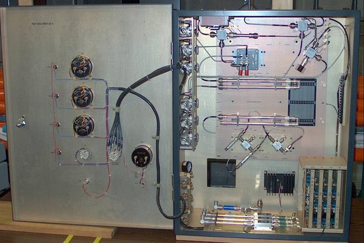 THE INSIDE OF THE FRONT PANEL DOOR OF THE MODEL 106 INTERFACE UNIT, is shown here on the test bench at Watts Antenna. Wiring to rotary switch controls, setpoint and power meters, alarm lamps, and test jacks is evident. The Model 106 interface unit does not contain an autophaser assembly. A view of the front of the door panel is shown in the photograph in the lower right corner on the cover.
MODEL 106 END-FIRE GLIDE SLOPE THEORETICAL PATTERNS (CATEGORY I)
The Watts Model 106 provides a unique capability to provide Category I service with limited available real estate. Because of the frangible design, the antennas can be placed within 25 feet of the runway edge with a limited shoulder area. The defined critical area also permits placement of the antennas between the runway and taxiway. The non-imaging characteristics of the design require the absolute minimum of conditioning of the local terrain resulting, in many cases, significant cost savings from the avoidance of extensive ground preparation. The Model 106 provides a proportional guidance area of 15 degrees. The course area antenna has a -2 dB beamwidth of only 5 degrees. The area outside, or clearance region, contains fly-up signal allowing remarkable performance for narrow corridor applications.
MODEL 106 AND MODEL 105 END-FIRE GLIDE SLOPE SYSTEMS SPECIFICATIONS
| Nomenclature | End-Fire Glide Slope Antenna System Model 106 | End-Fire Glide Slope Antenna System Model 105 |
| Frequency Range | 329 to 335 MHz | 329 to 335 MHz |
| Excitation:
CSB SBO CLR |
4.0 W (typical)
100 to 500 mW (as required) 400 mW to 2.5 W (as required) |
4.0 W (typical)
200 to 500 mW 400 mW to 2.5 W |
| Input Impedance | 50 ohms | 50 ohms |
| VSWR:
Main Antenna Clearance Antenna |
1.25:1
2.0:1 |
1.25:1
2.0:1 |
| Pressurization | Dry air, constant, 3 to 9 PSI, nominal (stable pressure preferred) | Dry air, constant, 3 to 9 PSI nominal, stable pressure preferred |
| System Air Volume | 6.60 cu. ft. (186.9 liters) (approximate)
with specified dielectric coaxial cables |
7.70 cu. ft. (218.0 litres) (approximate)
with specified dielectric coaxial cables |
| Dehydrator Run Time | 7.5 minutes (Andrew MT300 only)
1.4 hours in a 24-hour period (Andrew MT300 only) |
8.7 minutes to pressurize (Andrew MT300 only)
1.5 hours in a 24-hour period (Andrew MT300 only) |
| Dehydrator Idle Time | 2.1 hours between cycles (Andrew MT300 only)
22.6 hours in a 24-hour period (Andrew MT300 only) |
2.4 hours between cycles (Andrew MT300 only)
22.5 hours in a 24-hour period (Andrew MT300 only) |
| Radiation Pattern:
Main Antenna Clearance Antenna |
-2 dB beamwidth > 5 deg. azimuth
-10 dB beamwidth < 20 deg. azimuth Front to back ratio > 12 dB Maximum lateral radiation nominally -19 degrees and 11 degrees relative to the runway centerline with a null in the region of main antenna maximum radiation. Front to back ratio > 12 dB |
-2 dB beamwidth > 13 deg. azimuth
-10 dB beamwidth < 30 deg. azimuth Front to back ratio > 12 dB Maximum lateral radiation nominally -19 degrees and 11 degrees relative to the runway centerline with a null in the region of main antenna maximum radiation. Front to back ratio > 12 dB |
| Glide Angle | 2.5 to 4.0 degrees relative to horizontal (adjustable) | 2.5 to 4.0 degrees relative to horizontal (adjustable) |
| Path Width | 0.70 degree (Nominal) | 0.70 degree, (nominal) |
| Power Requirement | 22-30 VDC, (nominal 28 VDC) @ 0.78 amp | 22-30 VDC, (nominal 28 VDC) @ 0.98 amp maximum |
| Duty Cycle | Continuous, unattended | Continuous, unattended |
Our systems are universally designed to interface with any capture effect glide slope station equipment.