
WATTS ANTENNA COMPANY’S MODEL 201 LOCALIZER ANTENNA
HIGHLY DIRECTIONAL BEAM-STEERED SUPER-WIDE APERTURE LOCALIZER ANTENNA
CATEGORY I/II/III INSTRUMENT LANDING SYSTEM
FEATURING MINIMAL CRITICAL & SENSITIVE AREAS
The Watts Model 201 Highly Directive Localizer System provides final approach azimuth guidance information to a landing aircraft, enabling the pilot or autopilot to maintain the proper course during the approach and landing. The Model 201 is engineered to provide Category III ILS signal quality for the most complex airport environments in the world and represents R&D in ILS antenna system design well ahead of today’s standards.
Watts Antenna Company manufactures the World’s widest aperture ILS Localizer Antenna array producing the World’s narrowest ILS Localizer radiated signal beam!
Watts Antenna Company’s Model 201 Super-Wide Aperture Localizer Antenna
Dramatically Increase Your Airport’s Throughput Capacity!
-
Substantially Reduces ILS Critical and Sensitive Areas
-
Provides Maximum Runway Capacity, Allowing Increased Airport Development and New Construction.
-
Modular Course Antenna – Adjustable Antenna Aperture
-
Frangible Design
-
Minimize Coaxial Cable and Low Tune-Up Time – Adjustment by Trimming One Coaxial Cable
-
Three Configurations:
-
Model 201 Wide-Aperture Slotted Cable Course Antenna:
The narrow course beam produces Category III signal-in-space
course structure quality and adequate signal levels to meet
all FAA usable distance requirements.
-
The 8-Element LPD Reduced Clearance-Sector Antenna Array:
Provides limited azimuthal coverage with course roughness comparable
to a 14-element array since energy is suppressed outside +/- 15 degrees
in azimuth and meets usable distance.
-
The Model 201-8 Two Frequency Localizer System:
Combination of the Model 201 Wide-Aperture Slotted Cable Course
Antenna Array with the 8-Element LPD Reduced Clearance-Sector Antenna
Array meets all FAA Flight Inspection requirements.
CAT II/III INSTRUMENT LANDING SYSTEM
MODEL 201
WIDE APERTURE LOCALIZER ARRAY
BENEFITS
- Designed to Interface with the Electronic Equipment of any Manufacturer
- Can be Configured to Provide a Narrow Beam Back-course
- Long Term Category II/III Performance – Minimize Future Downtime and
Costs Associated with Periodic Upgrades of the ILS - Premium Quality Approach Course
- The Smallest Critical and Sensitive Areas of any ILS Localizer
- Provides Significant Opportunity to Increase the Number of Flight Operations
During IFR Conditions - Provides Significant Opportunity to Promote New Taxiways and Greater Use
of Existing Taxiways to Increase Flight Operations - Provides Substantial Opportunities to Permit New Construction on and
Around the Airport Property Without Degrading the ILS - Increased Confidence that all Airborne Receivers will Provide the Same
Indications on an Approach. i.e. Reduce Variations Between Flight
Measurement Systems that Results from Multipath Signals - Potential to Provide Efficient CAT II/III Operations with Super Jumbo Jets such as the Airbus A380
- Potential to Provide a Greater Density of ILS Localizer Systems and
Minimize Channel Assignment Constraints - Frangible Design – Thin Wall Fiberglass Tubing Construction
- Minimize Coaxial Cable Compared to Conventional Localizer Systems
- Reduced Tune-up Time
- Simplify Operating Frequency Changes
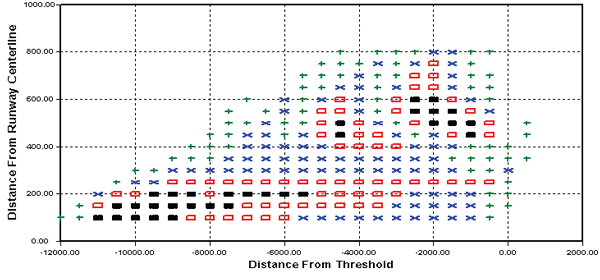
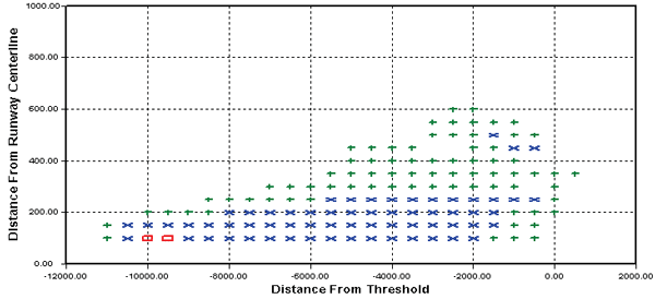
ILS CRITICAL AREA MODELING
CATEGORY II/III
SCENARIO — 747 AIRCRAFT PARALLEL TO THE RUNWAY
SOME SAID IT COULDN’T BE DONE…….WE DIDN’T LISTEN!
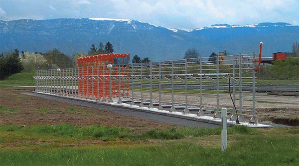
Typical 150 Feet Antenna Array Aperture (Course Only)
Watts 278 Feet Antenna Aperture (Course Only)
GREATER MOVEMENT OF AIRCRAFT WITHOUT DEGRADING THE ILS?
GREATER AIRPORT EFFICIENCY DURING POOR VISIBILITY?
YES!
MORE AIRCRAFT OPERATIONS PER HOUR!
SPECIFICATIONS
| COURSE ANTENNA (64 Slots) | |
| Antenna Aperture: | 278 Feet (84.7 Meters) |
| 3dB Beamwidth: | 2.65 Degrees Theoretical |
| Front-to-Back Ratio: | 0 to 20 dB (Adjustable with Reflecting Screen) |
| CSB Sidelobe Level Suppression: | = 27 dB or Greater |
| SBO Sidelobe Level Suppression: | > 27 dB, 31 dB Compared to Existing Systems |
| Course Width: | 3 to 4 Degrees (Adjustable) |
| Transmission Line: | 7/8 Air-Dielectric |
| System Air Pressure: | 5 PSI Nominal |
| CLEARANCE ARRAY (2 Types) | |
| Antenna Aperture: | 50 Feet ( 15.3 Meters) |
| Azimuth Coverage: | +/- 15 to 20 Degrees |
| Clearance Array Type 1: | 8-Element LPD , No Back-Course |
| Clearance Array Type 2: | 8-Element Dipole, With Back-Course |
| Front-to-Back Ratio, Array Type 1: | 25 dB or Greater |
| Front-to-Back Ratio, Array Type 2: | 0 to 20 dB (Adjustable with Reflecting Screen) |
| CSB Sidelobe Level Suppression: | > 30 dB Beyond 22 Degrees, Theoretical |
| SBO Sidelobe Level Suppression: | > 30 dB Beyond 22 Degrees, Theoretical |
| Centerline Power Separation Course-to-Clearance: |
15 dB (Minimum) |
AIRPORT EFFICIENCY AT ITS PEAK…………
The Watts Model 201 Highly Directive Localizer System provides final approach azimuth guidance information to a landing aircraft, enabling the pilot or autopilot to maintain the proper course during the approach and landing. The Model 201 is engineered to provide Category III ILS signal quality for the most complex airport environments in the world and represents R&D in ILS antenna system design well ahead of today’s standards.
OUR ADVANCED TECHNOLOGY PRODUCT LINE LEADS
THE INDUSTRY BY:
- Providing Substantial Increases in Airport Capacity
- Providing Precision Guidance in Difficult Airport Environment
- Facilitating Airport Growth Opportunities
- Simplifying Air Traffic Control Operations
- Improving Signal Quality
- Increasing Safety
- Reducing Aircraft Fuel Consumption
- Reducing Greenhouse Gas Emissions