Model 106 EFGS End-Fire Glide Slope Antennas
HAVE YOU BEEN TOLD THE “SAME OLD STORY”?
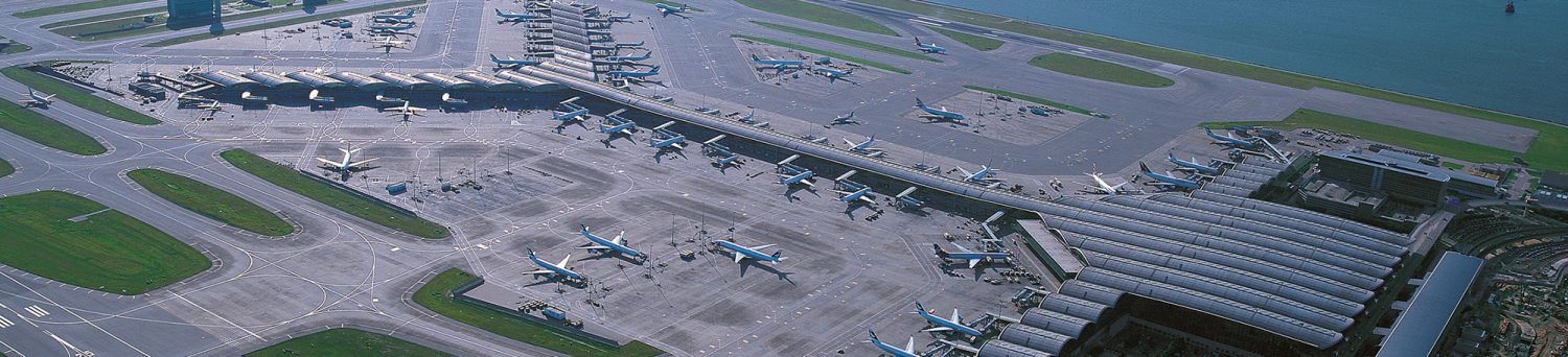
Have you been told that you cannot get ILS service at your airport because the site is too difficult? Throw that old report away! We don’t believe it & neither should you. Click the Airport Improvement Magazine link button below, read the article regarding one of our installed End-Fire Antennas & you will see why!
End-Fire Antennas Can Offer Numerous Benefits Over Conventional Image Systems:
- Significant Cost Savings by Avoiding Expensive Ground Plane Conditioning.
- Provide ILS Service where Previously not Possible or Cost Effective due to Terrain.
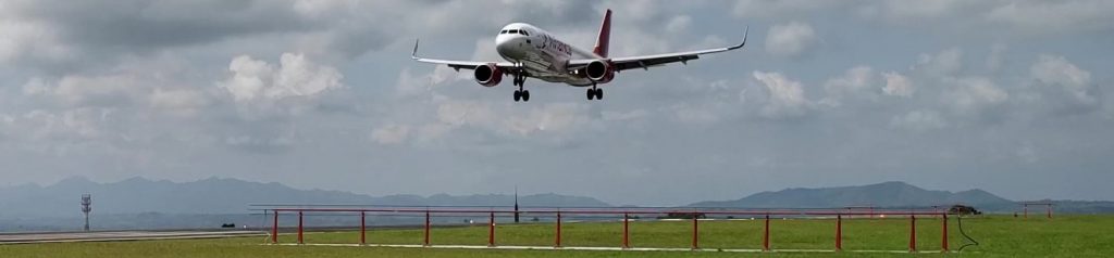
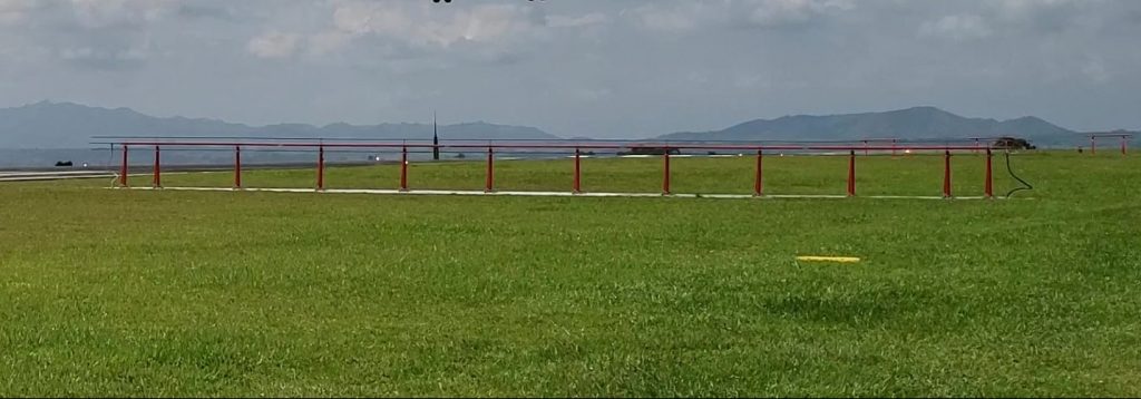
- Proven Frangible Low-Profile Design Permitting “Next to Runway” Installation.
- Save the Wetlands or Avoid High Wetland Relocation Costs.
- Waterside Installations Since the Signal is not Degraded by Tidal Variations.
- Precision Glide Path Guidance is Achieved with Narrow Lateral Radiation
- Patterns that Reduce Multi-path Signals from Buildings or Mountainous Terrain.
ANOTHER TOUGH SITE SOLUTION BY WATTS ANTENNA COMPANY
What About Improvements to Airport Efficiency?
The End-Fire Critical Area Size Is Substantially Smaller & Can Mean More Operations Per Hour!
End-Fire Glide Slope Antenna Systems
The Model 106 – For Category I ILS
CATEGORY I INSTRUMENT LANDING SYSTEM
WHEN NO ONE ELSE CAN DO IT!
MODEL 106
END-FIRE GLIDE SLOPE ANTENNA
FRONT ANTENNA AND A PROVEN FRANGIBLE SUPPORT STRUCTURE
THE EF-9 INTERFACE UNIT PROVIDES POWER DISTRIBUTION
AND MONITORING FOR THE ANTENNA SYSTEM
SPECIFICATIONS
| Frequency Range: | 329 to 335 MHz |
| Excitation: CSB SBO CLR |
4.0 W (typical) 100 to 500 mW (as required) 400 mW to 2.5 W (as required) |
| Input Impedance: | 50 ohms |
| VSWR: Main Antenna Clearance Antenna |
1.25:1 2.0:1 |
| Pressurization: | Dry air, constant, 3 to 9 PSI, nominal (stable pressure preferred) |
| System Air Volume: | 6.60 cu. ft. (186.9 liters) (approximate) with specified dielectric coaxial cables |
| Dehydrator Run Time: | 7.5 minutes (Andrew MT300 only) 1.4 hours in a 24-hour period (Andrew MT300 only) |
| Dehydrator Idle Time: | 2.1 hours between cycles (Andrew MT300 only) 22.6 hours in a 24-hour period (Andrew MT300 only) |
| Radiation Pattern:
Main Antenna Clearance Antenna |
-2 dB beamwidth > 5 deg. azimuth -10 dB beamwidth < 20 deg. azimuth Front to back ratio > 12 dB Maximum lateral radiation nominally -19 degrees and 11 |
| Glide Angle: | 2.5 to 4.0 degrees relative to horizontal (adjustable) |
| Path Width: | 0.70 degree (Nominal) |
| Power Requirement: | 22-30 VDC, (nominal 28 VDC) @ 0.78 amp |
| Duty Cycle: | Continuous, unattended |
| Outdoor Equipment: Temperature Relative Humidity Altitude Wind Ice Loading |
-50 to + 70 degrees C 5 to 100 percent 0 to 10,000 feet 0 to 100 mph 1 inch radial clear ice |
| Indoor Equipment: Temperature Relative Humidity Altitude |
-10 to +50 degrees C 5 to 90 percent 0 to 10,000 feet |
WATTS ANTENNA COMPANY
70 North Plains Road – Suite H
The Plains, Ohio 45780-1156
USA – Manufacturing Facility
Phone: +1.740.797.9380; Fax: +1.740.797.9787
WWW.WATTSANTENNA.COM
EMAIL: INFO@WATTSANTENNA.COM