THE PROOF IS IN THE CRITICAL AREA COMPUTATIONS!
Null-Reference Configuration For Critical Area Comparisons Of MODEL GP5-A1, Kathrein & FA8976 Antenna Arrays
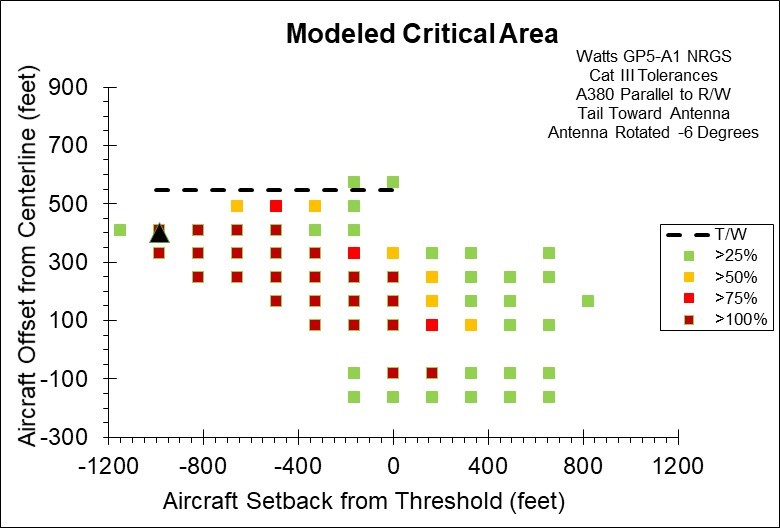
GP5-A1 NRGS w/Additional -6 Degree Rotation

Figure 1. Computed ILS Glide Slope Critical Area for an Airbus A380 Parallel to the Runway Using the Watts Model GP5-A1 Beam Steered Directional Antenna in a Null Reference (NR) Configuration. This Figure Shows the Addition Critical Area Reduction Achieved by Mechanically Rotating the Already Canted Beam by an Additional 6.0 Degrees Toward the Runway. The Dashed Line on the Plot Represents a Taxiway Offset Distance Where the Tower to Wingtip Separation is Only 5 Meters (16.4 Feet). The Black Triangular Shape Represents the Location of the Glide Slope Tower.
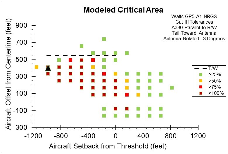
GP5-A1 NRGS w/Additional -3 Degrees Rotation
GP5-A1 NRGS W/O Additional Rotation
Figure 2. Computed ILS Glide Slope Critical Area for an Airbus A380 Parallel to the Runway Using the Watts Model GP5-A1 Beam Steered Directional Antenna in a Null Reference (NR) Configuration. This Figure Shows the Addition Critical Area Reduction Achieved by Mechanically Rotating the Already Canted Beam by an Additional 3.0 Degrees Toward the Runway. The Dashed Line on the Plot Represents a Taxiway Offset Distance Where the Tower to Wingtip Separation is Only 5 Meters (16.4 Feet). The Black Triangular Shape Represents the Location of the Glide Slope Tower.
Figure 3. Computed ILS Glide Slope Critical Area for an Airbus A380 Parallel to the Runway Using the Watts Model GP5-A1 Beam Steered Directional Antenna in a Null Reference (NR) Configuration. The Dashed Line on the Plot Represents a Taxiway Offset Distance Where the Tower to Wingtip Separation is Only 5 Meters (16.4 Feet). The Black Triangular Shape Represents the Location of the Glide Slope Tower.
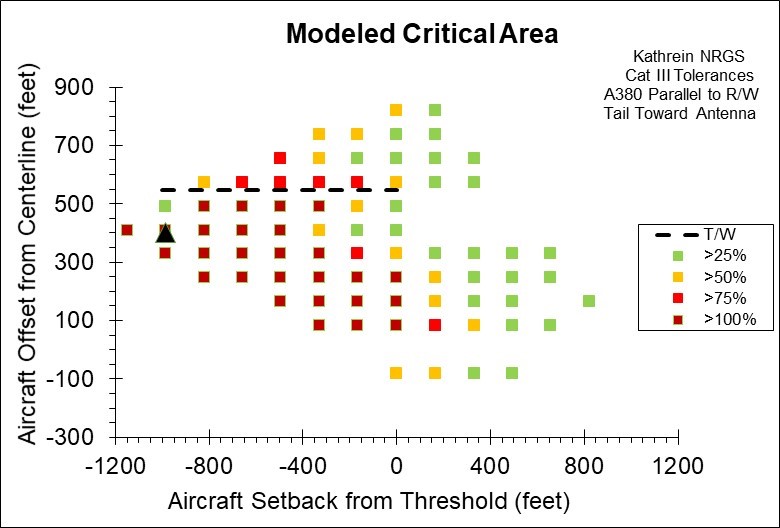
Kathrein NRGS
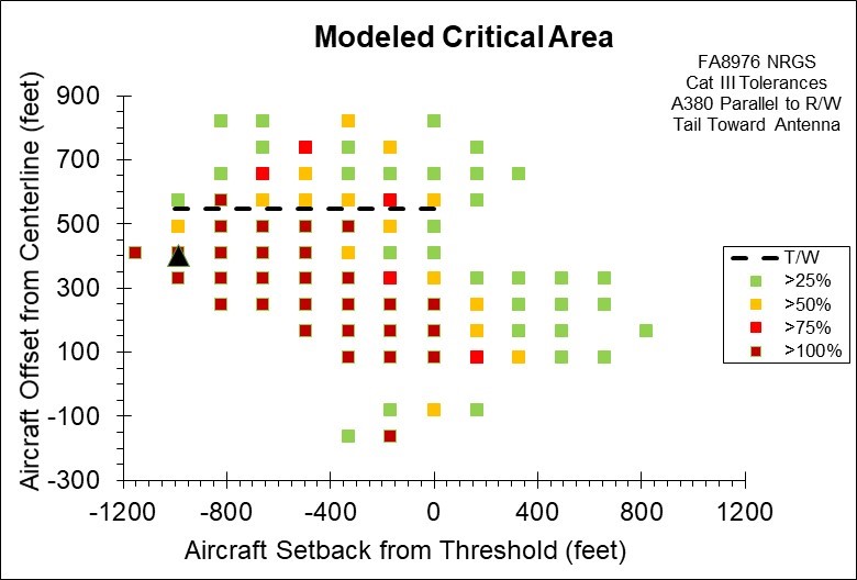
FA8976 NRGS
Figure 4. Computed ILS Glide Slope Critical Area for an Airbus A380 Parallel to the Runway Using the Kathrein Antenna in a Null Reference (NR) Configuration. The Dashed Line on the Plot Represents a Taxiway Offset Distance Where the Tower to Wingtip Separation is Only 5 Meters (16.4 Feet). The Black Triangular Shape Represents the Location of the Glide Slope Tower.
Figure 5. Computed ILS Glide Slope Critical Area for an Airbus A380 Parallel to the Runway Using the FA8976 Antenna in a Null Reference (NR) Configuration. The Dashed Line on the Plot Represents a Taxiway Offset Distance Where the Tower to Wingtip Separation is Only 5 Meters (16.4 Feet). The Black Triangular Shape Represents the Location of the Glide Slope Tower.


